HDL
Preparing an own ASIC requires a prototype circuit described in one of the Hardware Description Language(HDL). In this chapter you will prepare a design of 4-bit counter and a testbench for simulations. Before starting simulations install Verilator.
sudo apt install verilator -y
Design
Describe a counter presented below using submodules in a RTL architecture. Use a below template in Verilog language, it will make simulations easier. Create a file named counter.v, copy a below text and write a code for all modules.
module jk_ff ( input j,
               input k,
               input clk,
               output reg q);

endmodule

module and_2( input a,
              input b,
              output y);

endmodule

module counter( input clk,
                output [3:0] q,
	        output p);

endmodule

Simulation
Create file named tb.v and copy below text.
module tb_counter;

reg clk;

wire [3:0]q;
wire p;

counter u0 ( .clk(clk),
	 .q(q),
         .p(p));

initial begin
$dumpfile("test.vcd");
$dumpvars;
	clk = 1;
	#320 $finish;
end

always #10 clk=~clk;

always #20 $display("%d %d",p,q);

endmodule
To run a simulation use Verilator. The line below will compile testbench to binary version.
verilator --trace --binary -j 0 tb.v
You can run simulation typing ./obj_dir/Vtb in a terminal.
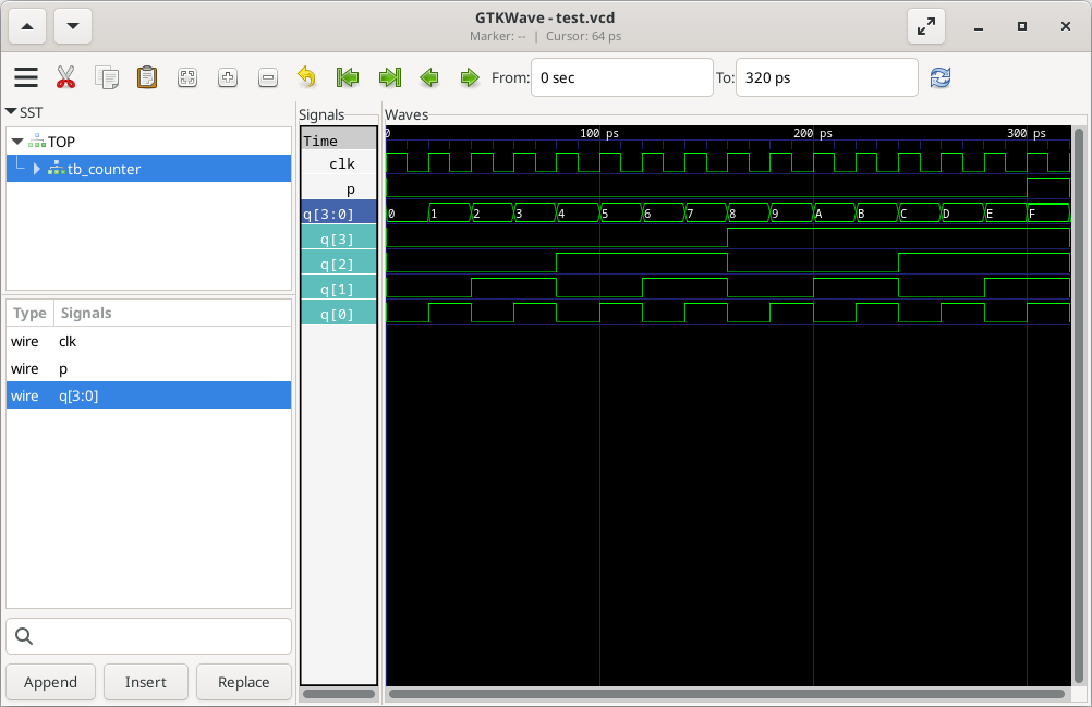
Type gtkwave test.vcd in the terminal to see the results in the time domain.
